Toggle LED
Note
Open GOWIN IDE as an administrator.
Create a Project
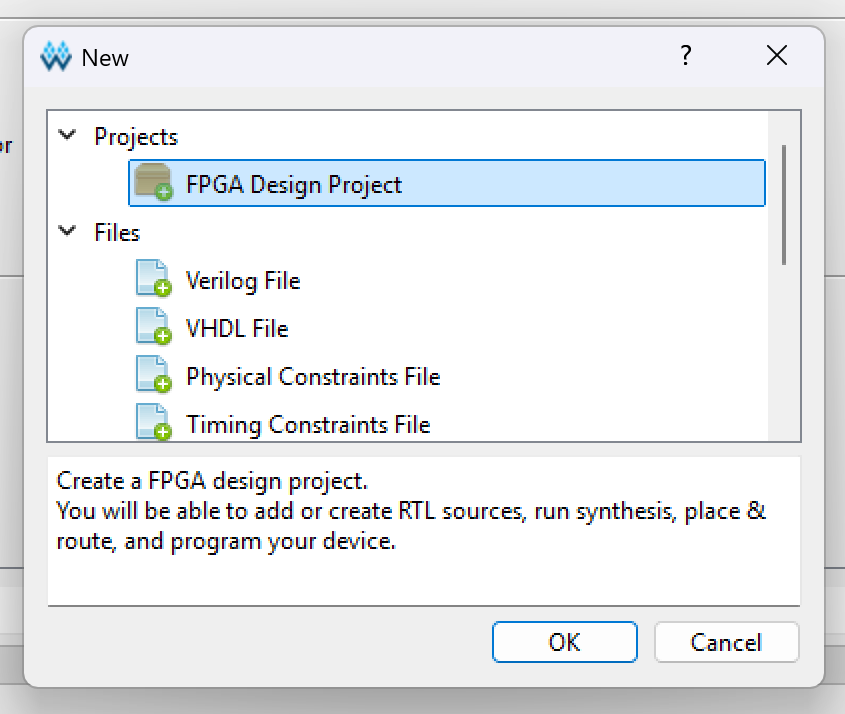
- New project: File-->NEW-->FPGA Design Project-->OK
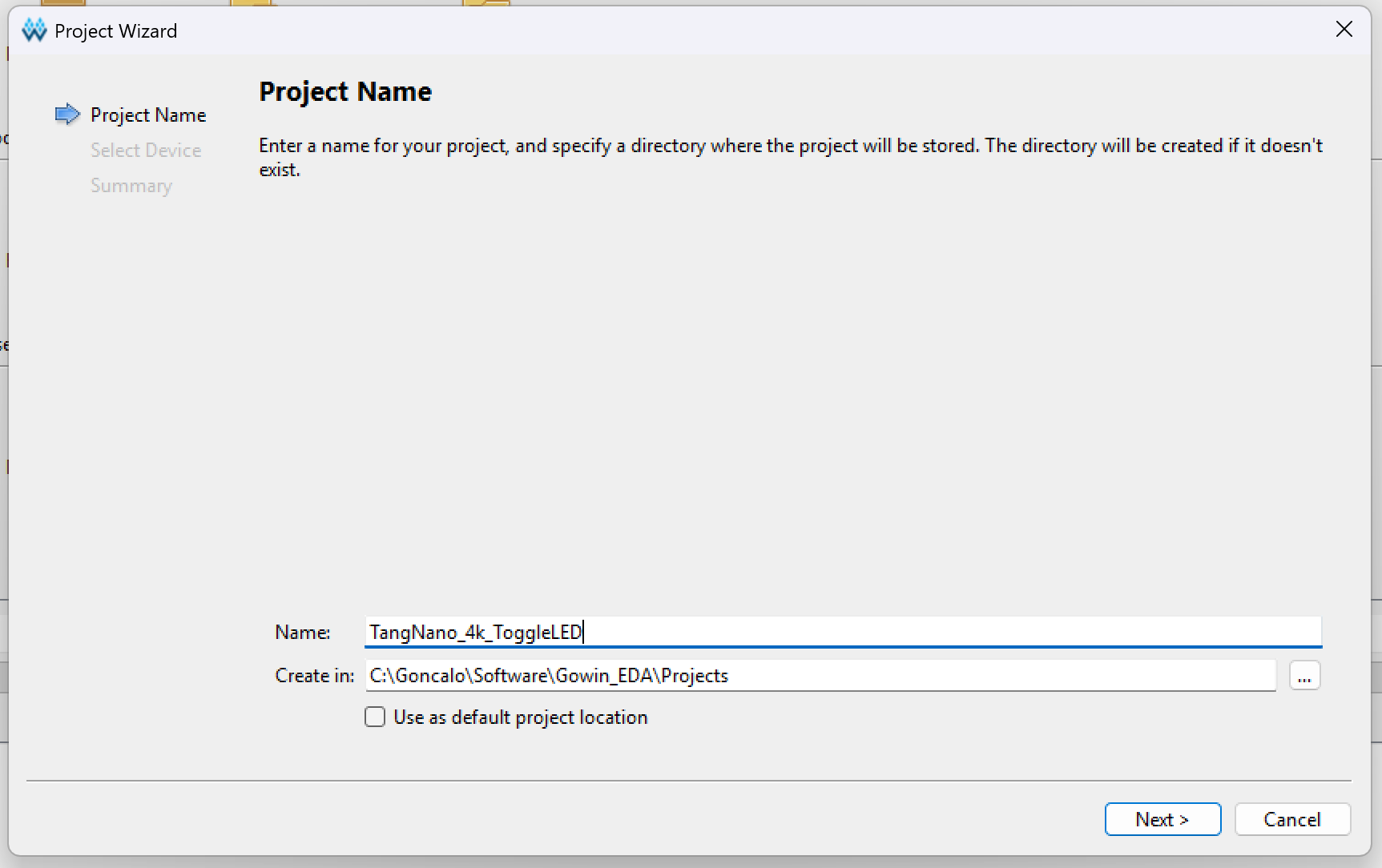
- Set the project name and path
- Choose the model of your FPGA: GW1NSR-LV4C
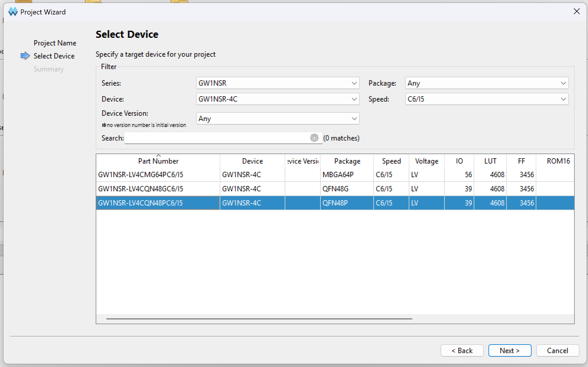
- Press next and finish.
Create the Top Level Module
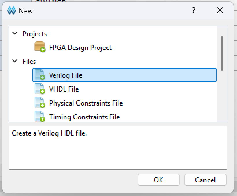
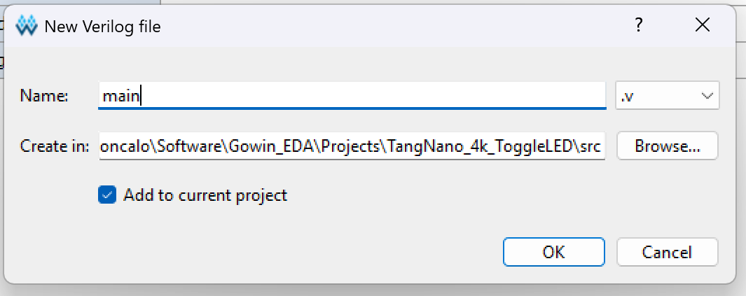
- Create a new Verilog file
- I like to call the top level module "main.v"
- Write the code below to toggle an onboard LED
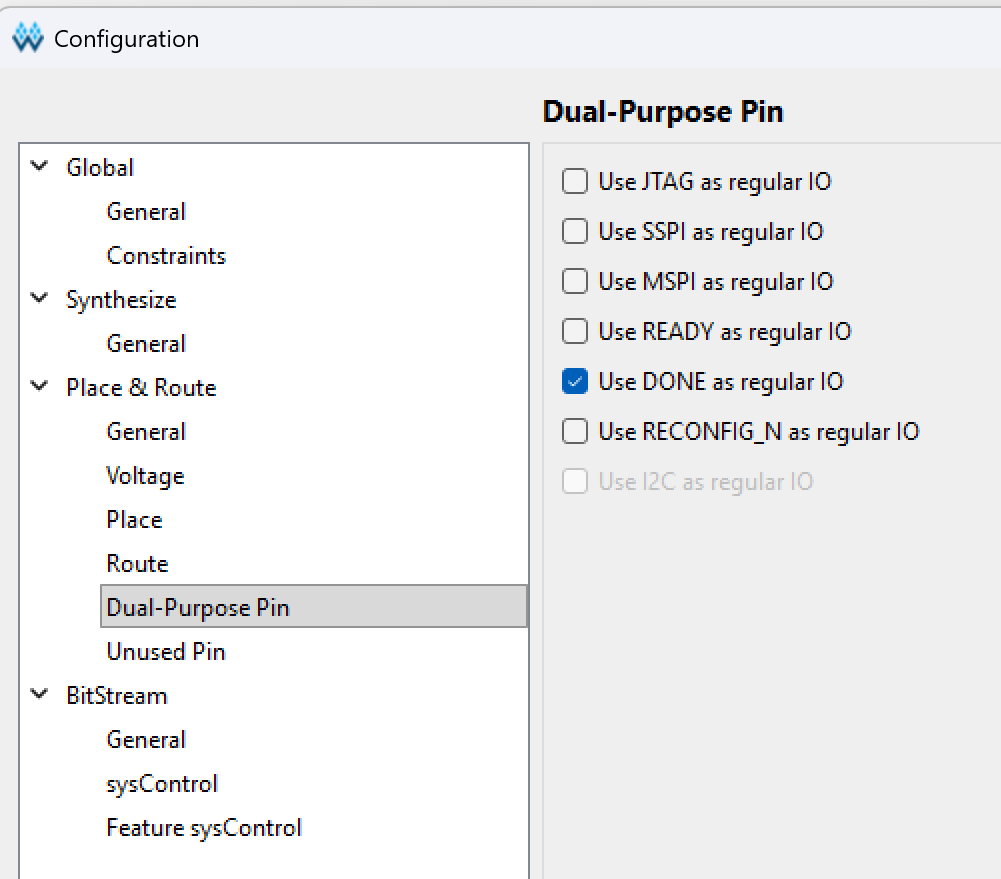
Note
After completing the code above, go to "Project -> Configuration -> Place&Route -> Dual-Purpose Pin" and check "Use DONE as regular IO", otherwise when synthesizing the project will report an error.
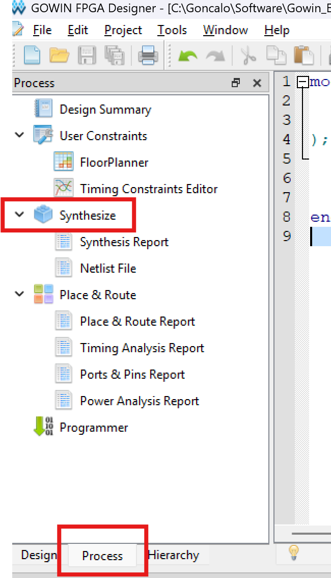
Synthesis
- Select the "Process" tab and click on "Synthesize"
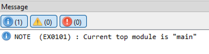
- If everything goes well you should see something like this
Constraints
- There are no clock constraints involved here
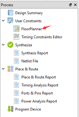
Floor Planner
- In order for FPGA to realize the functions of the code, the ports involved in the code must be bound to the actual pins of FPGA.
- Click on the FloorPlanner
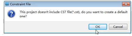
The first time you open it, a pop-up message will pop up saying that the .cst file is missing. Just select "OK";
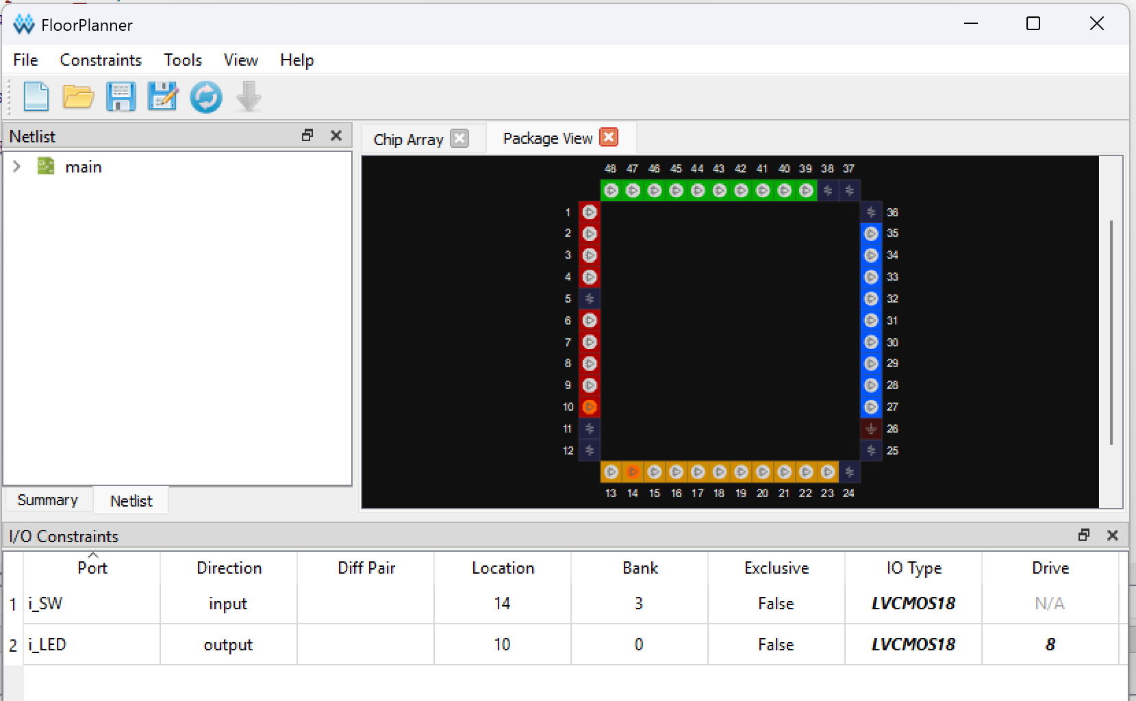
- Check the pins on the datasheet that you want to use
 - And assign them on the Floor Planner netlist.
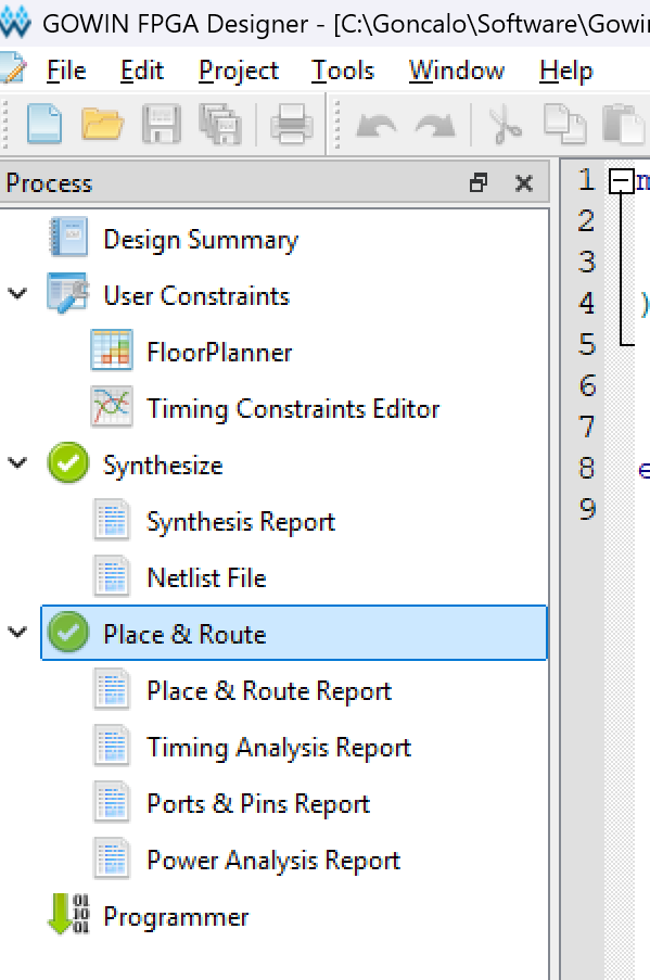
Layout and Routing
- Run the Place and Route
- If all goes well, you should have something similar to the picture below
Download to Device
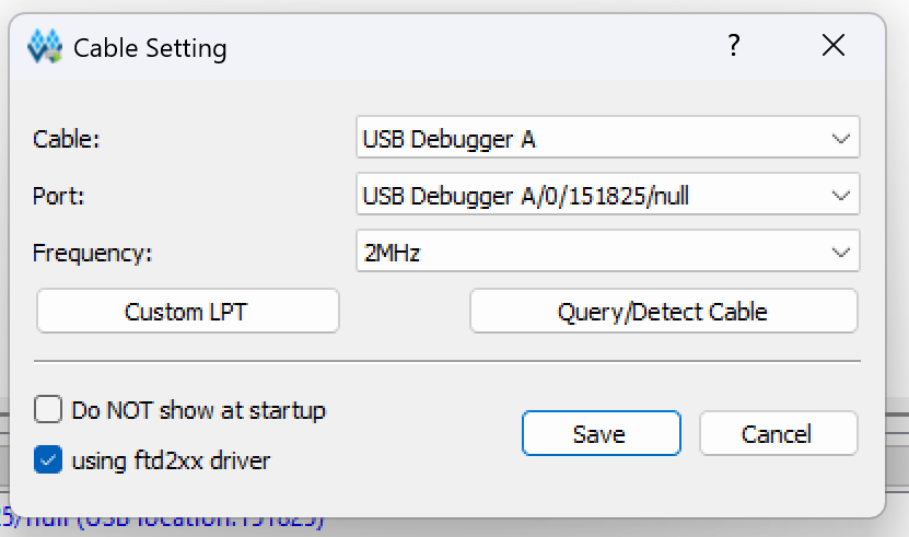
- Double click on "Programmer" and select the USB Debugger that will be use to program the board
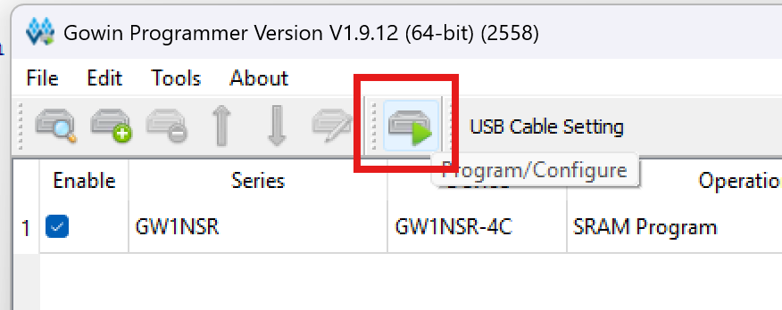
- Press "Program/Configure"
- Press the button to toggle the LED