Ultrasonic Sensor
Introduction
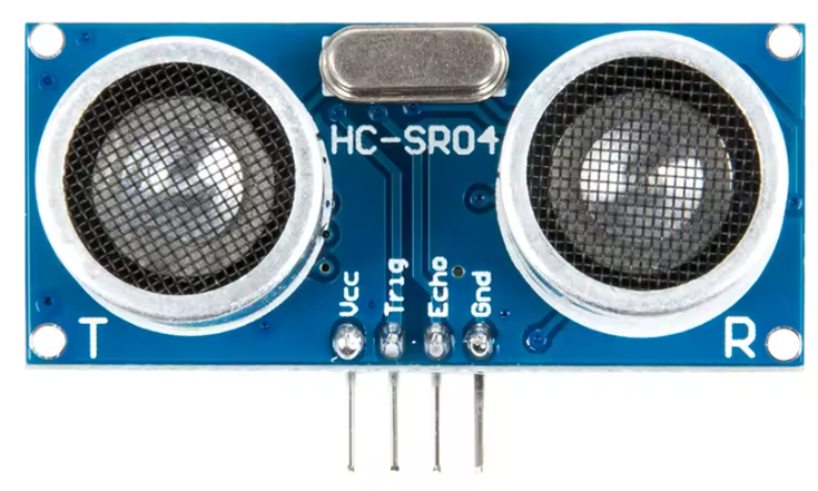
In this article we are going to design and write the code in Verilog to interface the HC-SR04 ultrasonic sensor.
Warning
Warning
From the datasheet we need to pay attention to a couple of specs so we don't damage the DE10-Lite FPGA board.
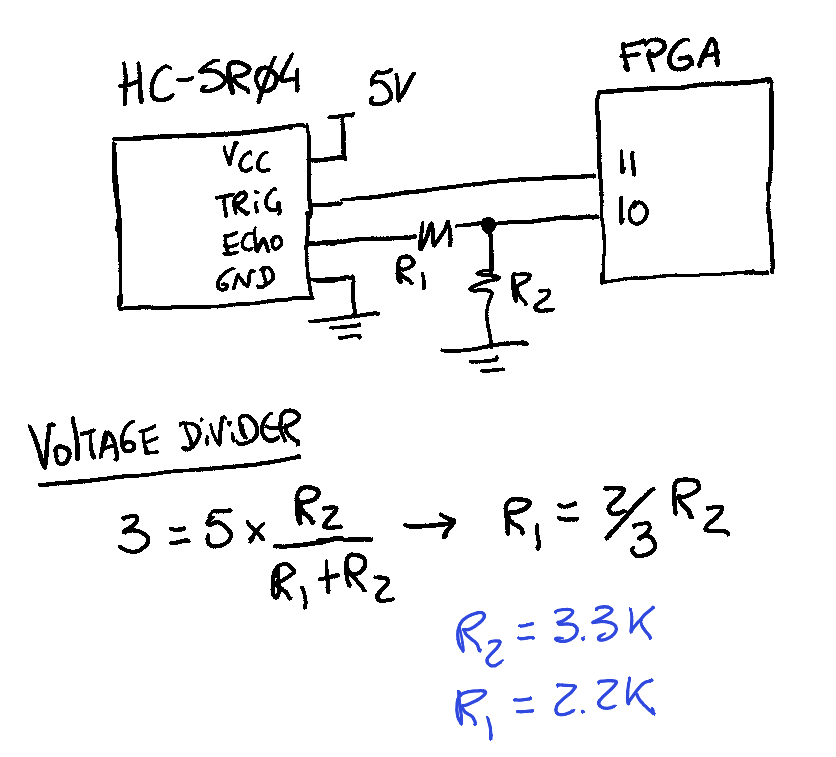
The HC-SR04 works at 5V, which means that the echo pin of the board can potentially damage the input pin of the FPGA that is going to read that pulse. Before connecting that pin to the FPGA, make sure that you have a voltage divider to drop the voltage down to a 3V3 logic level.
Note
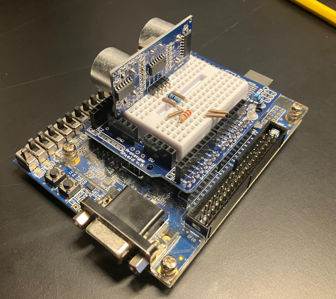
The DE10-Lite has an Arduino expansion header available so we can connect Arduino shields and avoid having a bunch of wires connecting thins around. Super convenient 🙂
Schematic
Design Stage
Let's start by reviewing the required HC-SR04 signals:
- "You only need to supply a short 10uS pulse to the trigger input to start the ranging, and then the module will send out an 8 cycle burst of ultrasound at 40 kHz and raise its echo."
- "The Echo is a distance object that is pulse width and the range in proportion. You can calculate the range through the time interval between sending trigger signal and receiving echo signal."
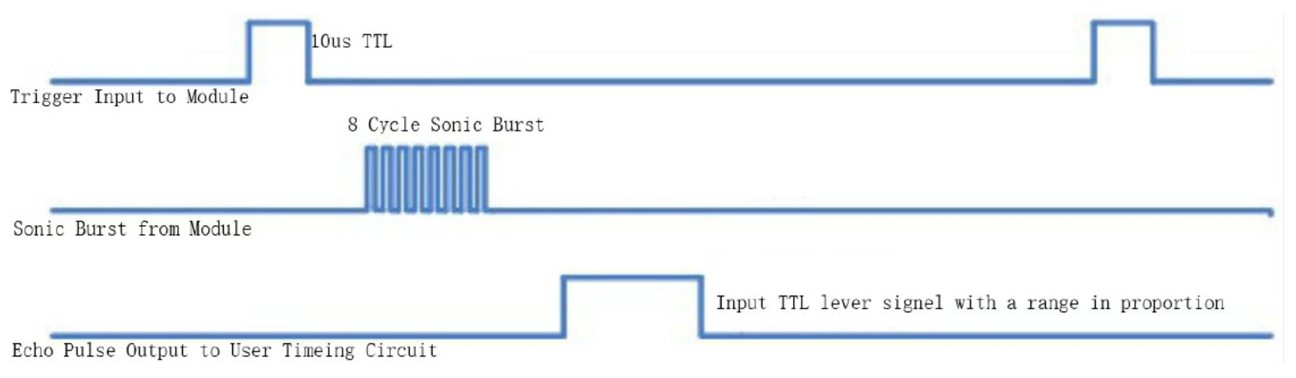
- "Formula: uS / 58 = centimeters or uS / 148 =inch; or: the range = high level time * velocity (340M/S) / 2; we suggest to use over 60ms measurement cycle, in order to prevent trigger signal to the echo signal."
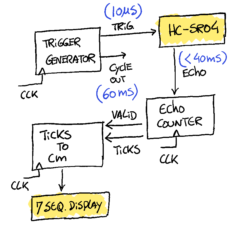
Block Diagram
The modules with a white background will be developed inside the FPGA, the rest of the modules are external components to the FPGA.
Implementation Stage
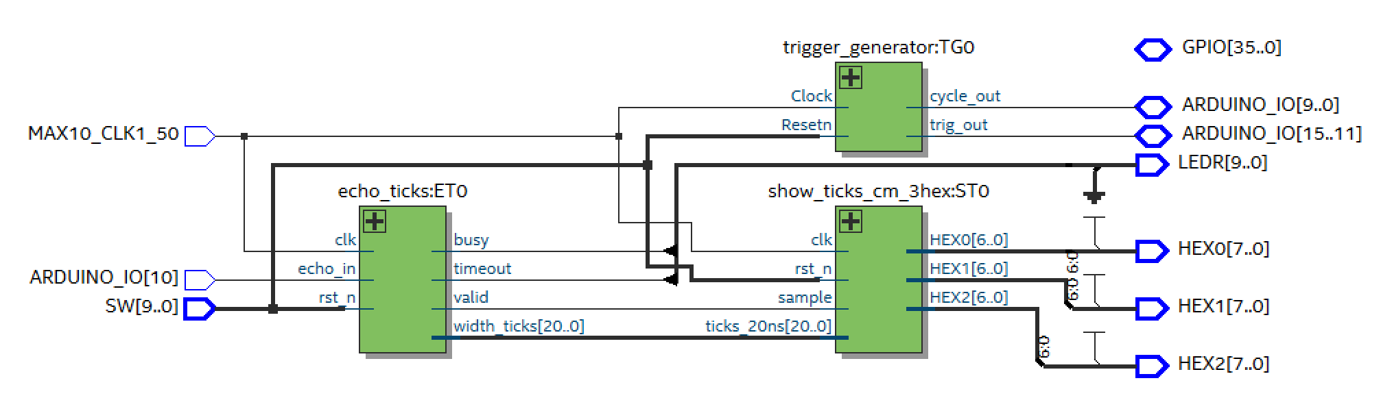
Top Module
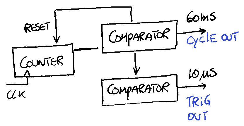
Trigger Generator Module
Block Diagram
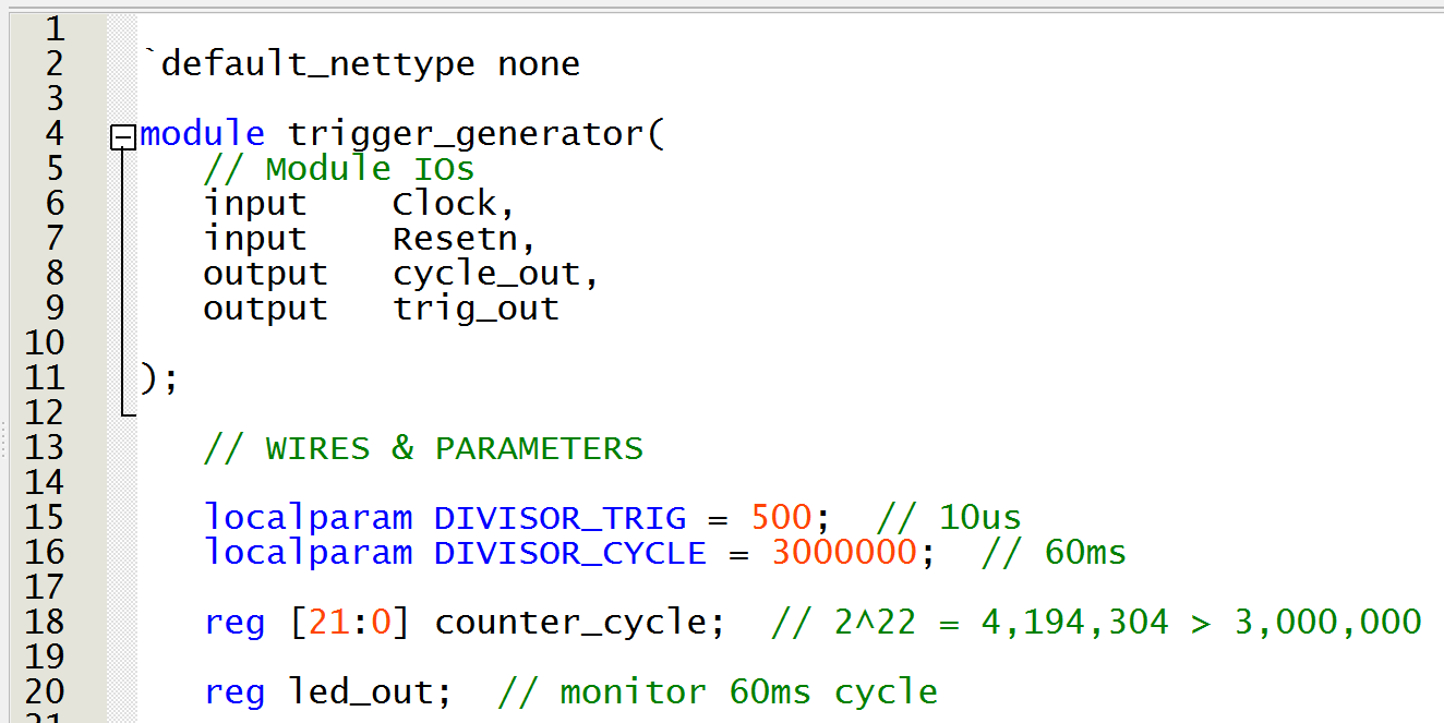
Code Description
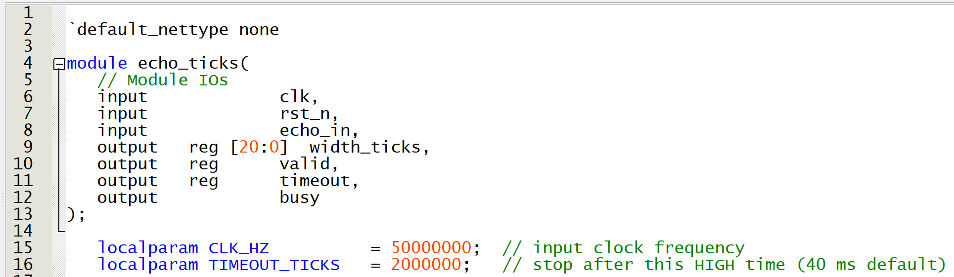
- Line 2: disable implicit net declarations. Any undeclared identifier becomes a compiler error.
- Lines 4 to 11: module header
- Clock explanation: the DE10-Lite runs at 50MHz clock -> 20 ns.
- Line 15: if we count 500 * 20ns = 10us
- Line 16: if we count 3000000 * 20ns = 60ms
- Line 17: to count up to 60ms we need 22 bits -> $2^{22}=4,194,304 > 3,000,000$
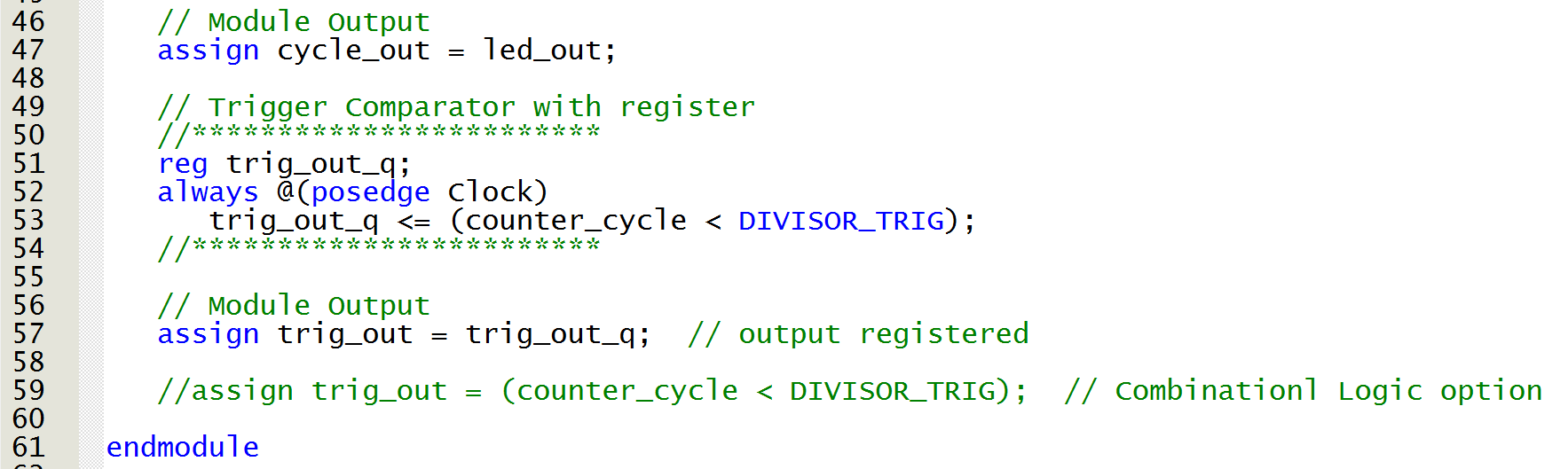
- Lines 24 to 43: 22 bit counter, with asynchronous reset, and resetting counting @ 3000000. The led_out variable is there for monitoring reasons.
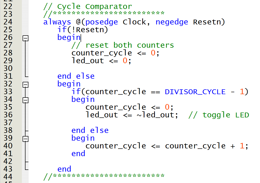
- Lines 51 to 53: 10us pulse to the HC-SR04 trigger input.
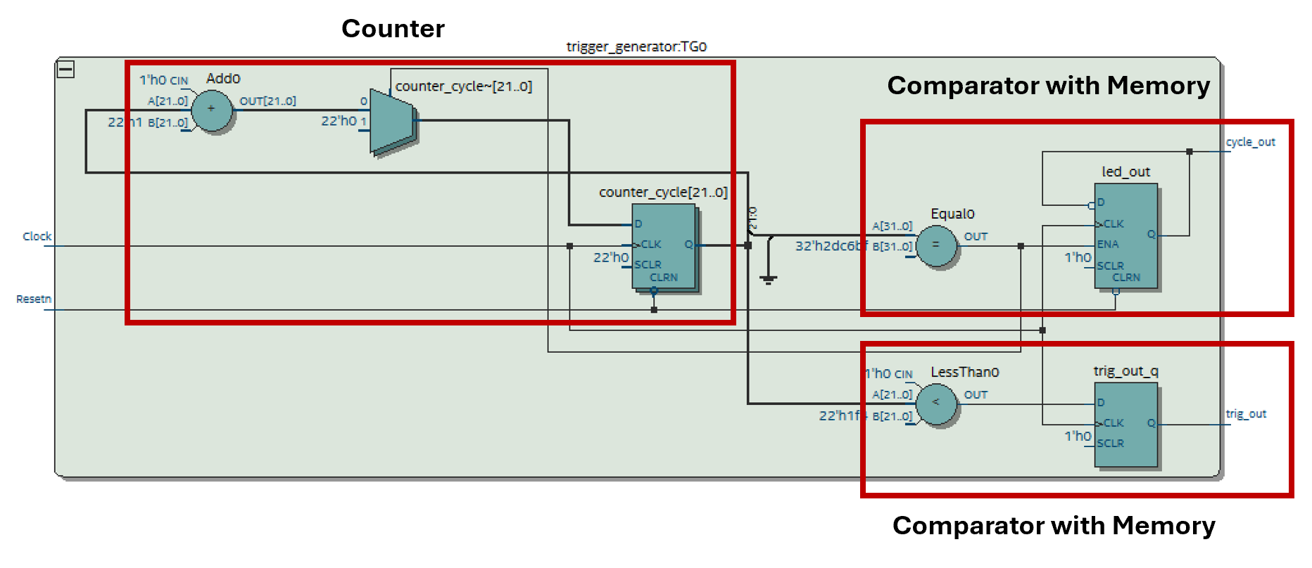
RTL Output
Echo Ticks Module
Block Diagram
Code Description
- Line 2: disable implicit net declarations. Any undeclared identifier becomes a compiler error.
- Lines 4 to 13: module header
- Clock explanation: the DE10-Lite runs at 50MHz clock -> 20 ns.
- Line 15: we will be sampling the echo pin at the fastest rate possible, in this case 20ns
- Line 16: if we count 2000000 * 20ns = 40ms
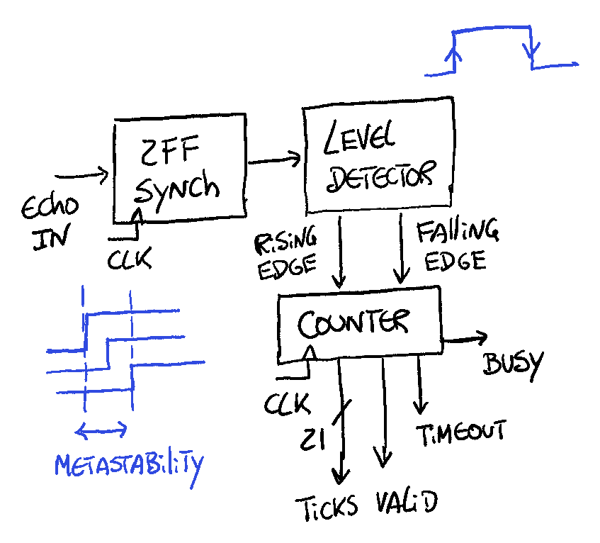
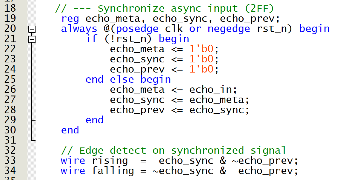
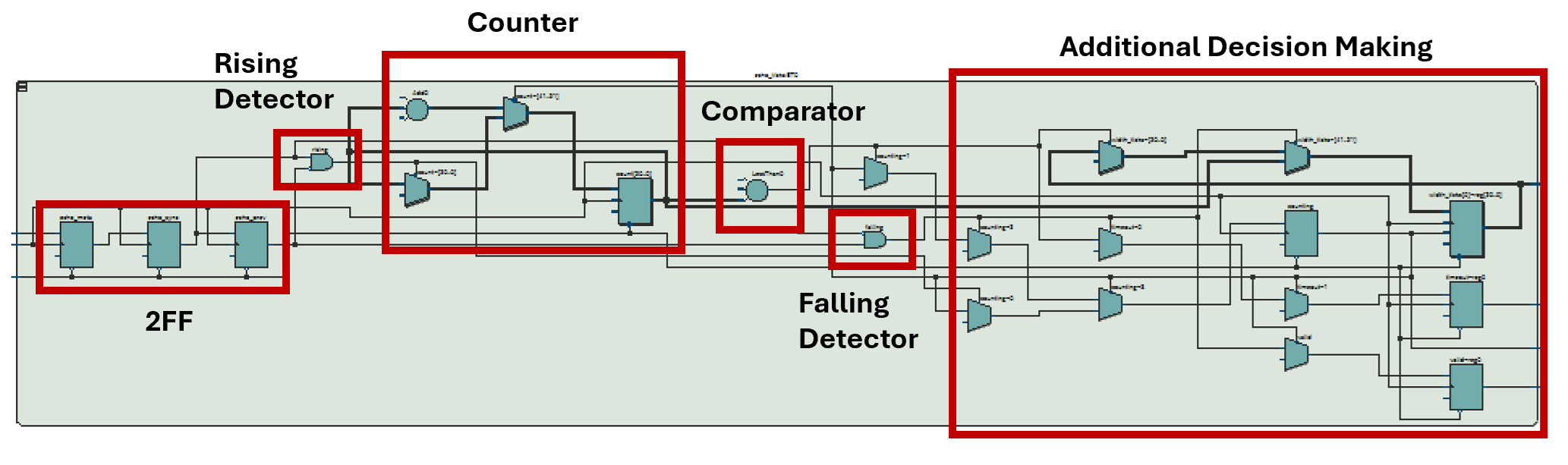
- Lines 19 to 30: 2-flip-flop (2FF) synchronizer. External pins are asynchronous, and without the 2FF synchronizer, we risk metastability corrupting the whole design. Two FFs dramatically reduce the risk and make the input safe for our logic.
- Line 33: rising edge detector
- Line 34: falling edge detector
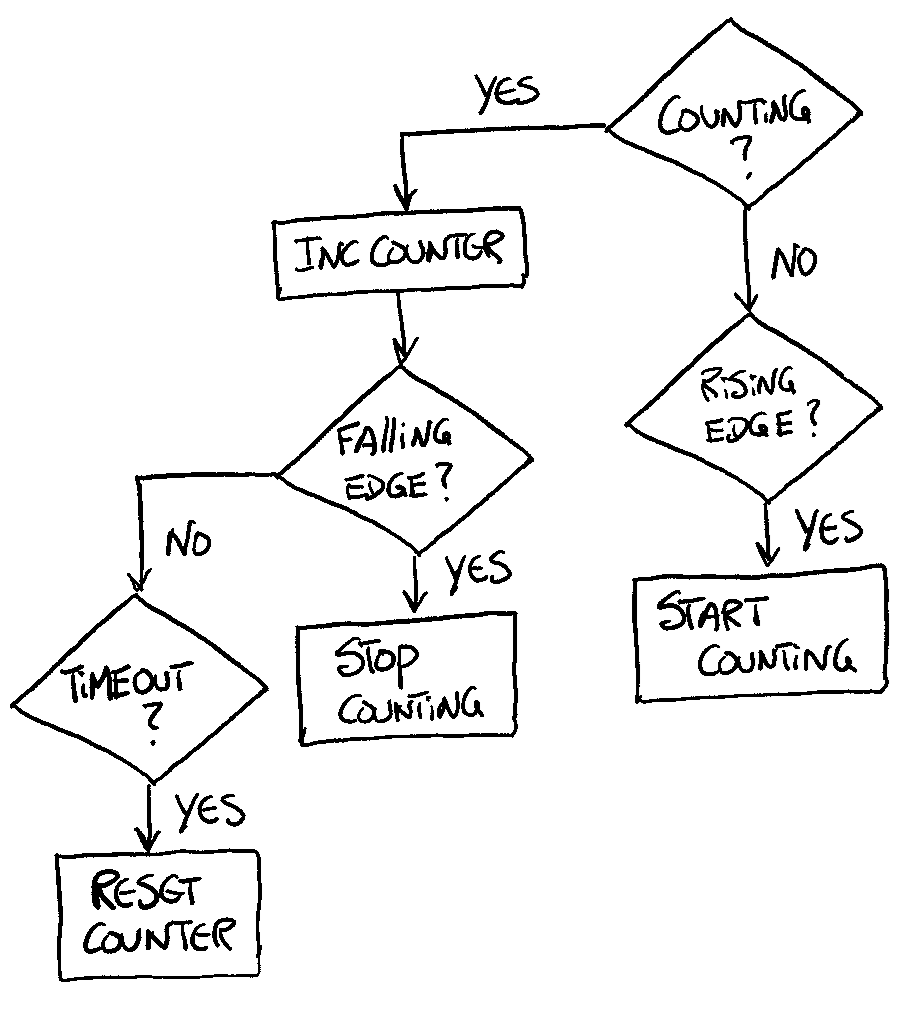
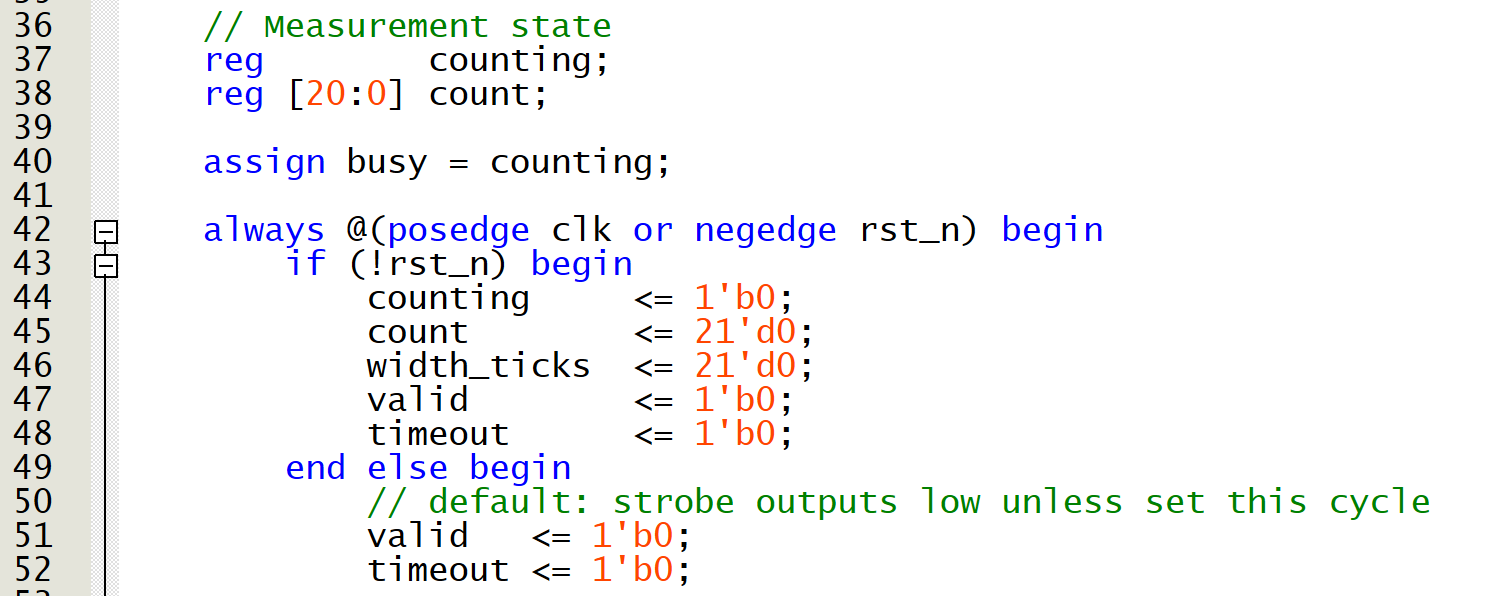
- Lines 42 to 77: the counter is encapsulated with a simple algorithm done with if statements.
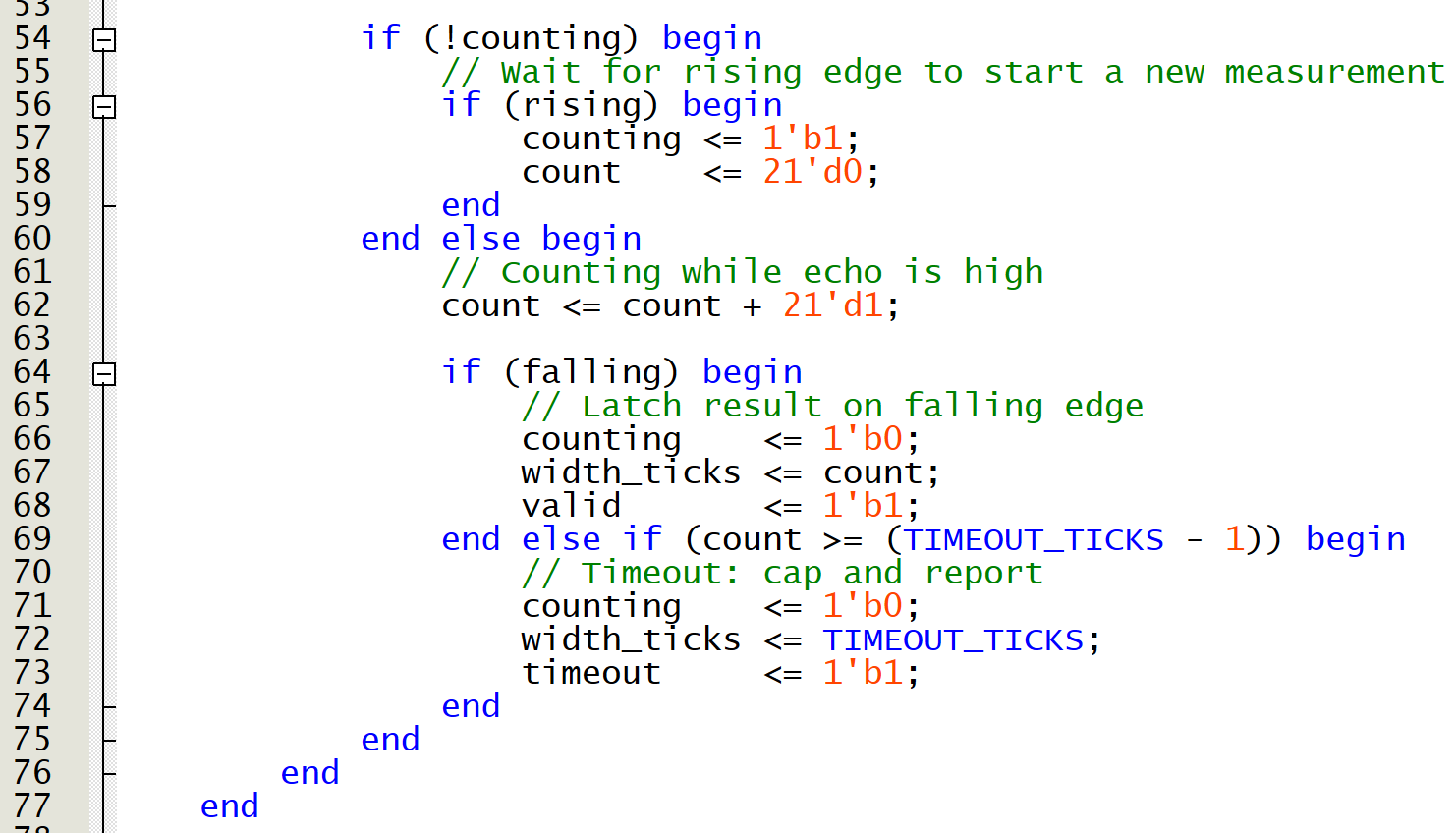
Note
In a sequential always block (e.g. always @(posedge clk) ), missing an else is not a problem. No latch is inferred because the block already infers a flip-flop, not combinational logic.
RTL Output
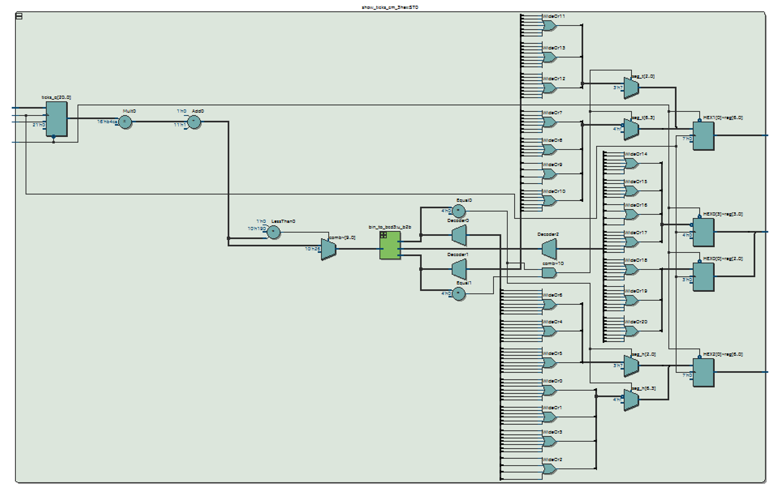
Show Ticks in cm
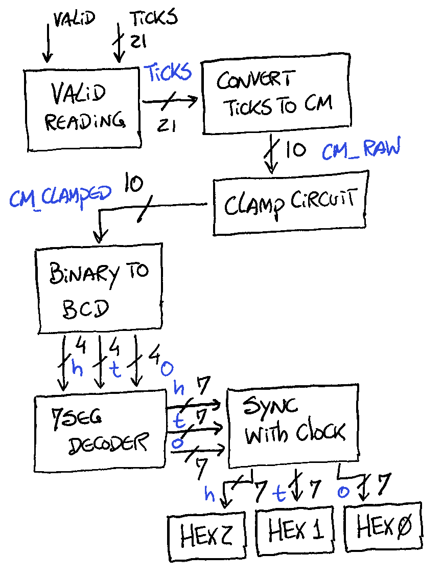
Block Diagram
Code Description
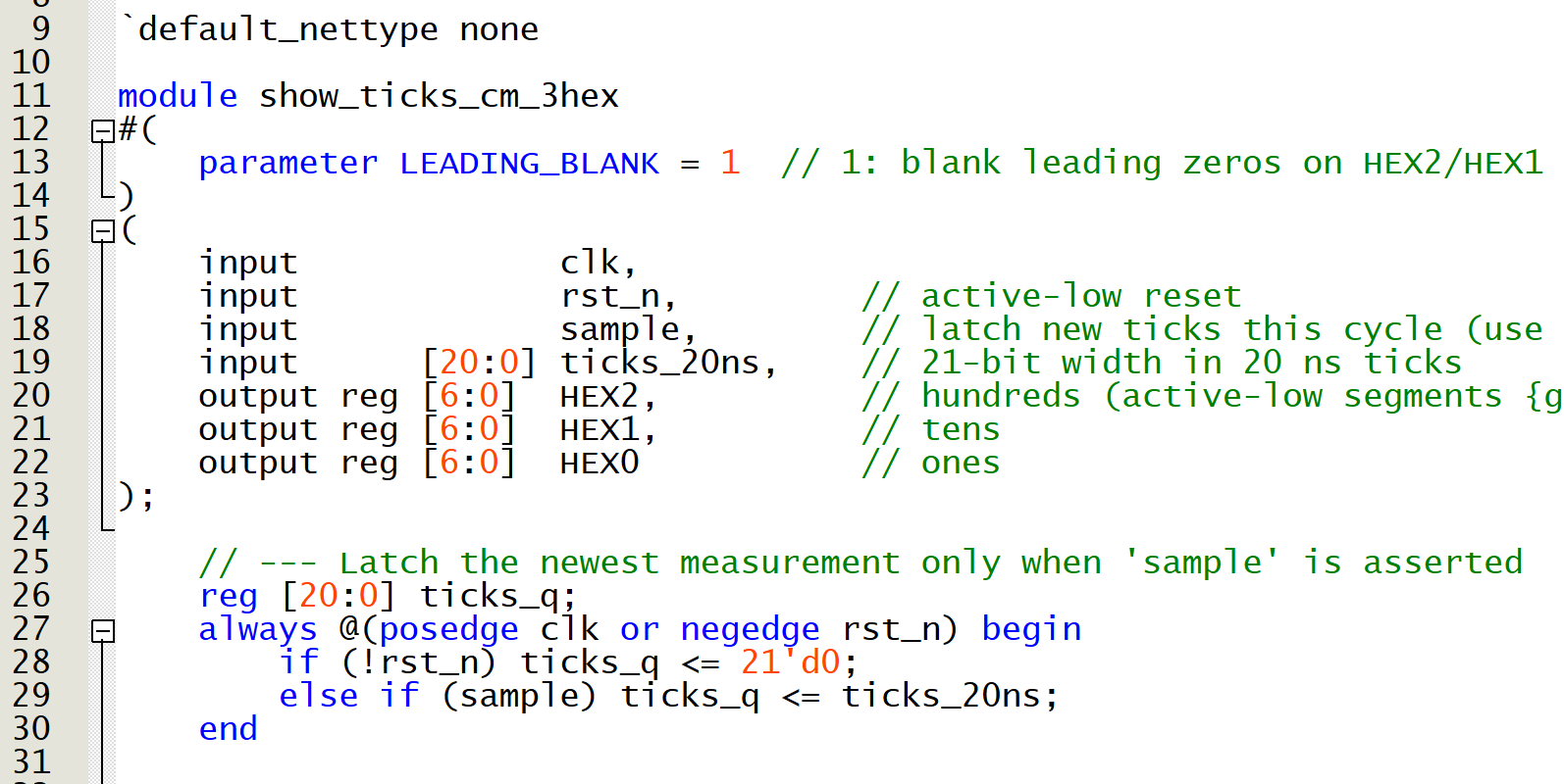
- Line 9: disable implicit net declarations. Any undeclared identifier becomes a compiler error.
- Lines 11 to 23: module header
- Clock explanation: the DE10-Lite runs at 50MHz clock -> 20 ns.
- Lines 26 to 30: if there is a valid reading, then clocks the new tick sample
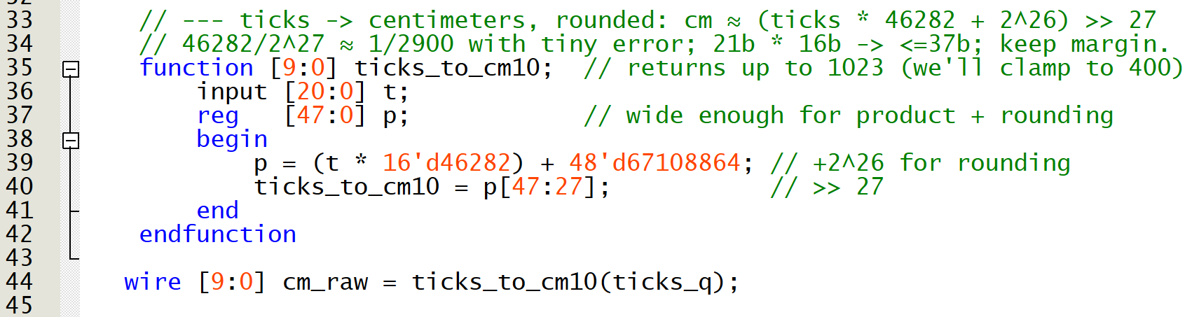
- Line 35 to 42: function that converts ticks to cm
- From the HC-SR04 datasheet the conversion formula is $cm \approx \frac{\mu s}{58}$
- That means that 1 cm takes $58\mu s$
- With the clock running at 20ns that equates to 2900 ticks $\left( \frac{58\mu s}{20 ns} \right)$
- We can apply this equation $cm=\left( \frac{ticks}{2900} \right)$ to get cm from ticks
Note
We could write the code just like this, but the synthesizer will infer a divider, which is large and slow.
-
An alternative is to take advantage of the DSP blocks and apply a multiply + shift algorithm (fixed-point math) to perform the division in a much cheaper and faster way with the cost of precision.
- With binary numbers if you divide a number by a power of two, that is equivalent to perform a right shift. A couple of sanity checks:
- $\frac{10}{2^1}=5$ equivalent to do $1010 >> 1 = 0101$
- $\frac{100}{2^3}=12.5$ equivalent to do $01100100 >> 3 = 1100$
- $\frac{46282}{2^{10}}=45.197$ equivalent to do $1011 0100 1100 1010 >> 10 = 101101$
- Remember you lose precision but if your application can tolerate that, this is very cheap to do in hardware
- Unfortunately, $2900 \neq 2^N$ so we need to replace our division with some sort of multiplication and shifting that satisfies the following formula: $$\frac{1}{2900} \approx \frac{K}{2^{S}}$$
- A good selection of S will depend on what we choose for our $K$.
- It is important to remember that the equation to find cm is now the following: $$cm = \frac{ticks \cdot K}{2^S}$$
- We are multiplying $K$ with ticks, and now the size of $K$ will depend on the size of the multiplier blocks on our FPGA.
- 16 bits multiplier is a typical value for a DSP multiplier block, which gives you $2^{16}=65536$
- Our $K$ shouldn't exceed that value
- Let's rewrite the generic formula again: $$K \approx \frac{2^S}{2900}$$
- A good compromise is to make $S = 27$ leading to a $K = 46282$
- The formula is now: $$cm = \frac{ticks \cdot 46282}{2^{27}}$$
- However, what is written in the code is: $$cm = \frac{ticks \cdot 46282 + 2^{26}}{2^{27}}$$
- We are only missing the explanation for that addition of $2^{26}$
- That last addition is rounding the multiplication to the nearest integer, for example:
- if $q = 3.2 \to 3$
- if $q = 3.7 \to 4$
- if $q$ is exactly half way, we must choose a tie rule:
- Half-up: $3.5 \to 4$
- Banker's (to even): $3.5 \to 4$, $2.5 \to 2$
- In fixed-point hardware we don't use floating point, we work with integers and power of two.
- To round to the nearest (half up) we add half of the divisor first, then shift. Let's go over some examples with smaller numbers, and use $S = 3$
- $\frac{11}{2^3} = 1.375$
- $11 + 2^2 = 15$
- $(1111)_2 >> 3 = (1)_2 = 1$
- Another Example
- $\frac{12}{2^3} = 1.5$
- $12 + 2^2 = 16$
- $(10000)_2 >> 3 = (10)_2 = 2$
- We have the result in cm (ticks_to_cm10 variable) with 20 bits $\to 2^{20} = 1048576$
- The maximum detection range of the sensor is 400 cm so 10 bits $\to 2^{10} = 1024$ is more than sufficient for our application.
- With binary numbers if you divide a number by a power of two, that is equivalent to perform a right shift. A couple of sanity checks:
-
Line 44: get raw cm conversion
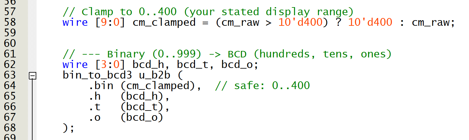
- Line 58: if the cm value is bigger than 400 then clamped to 400
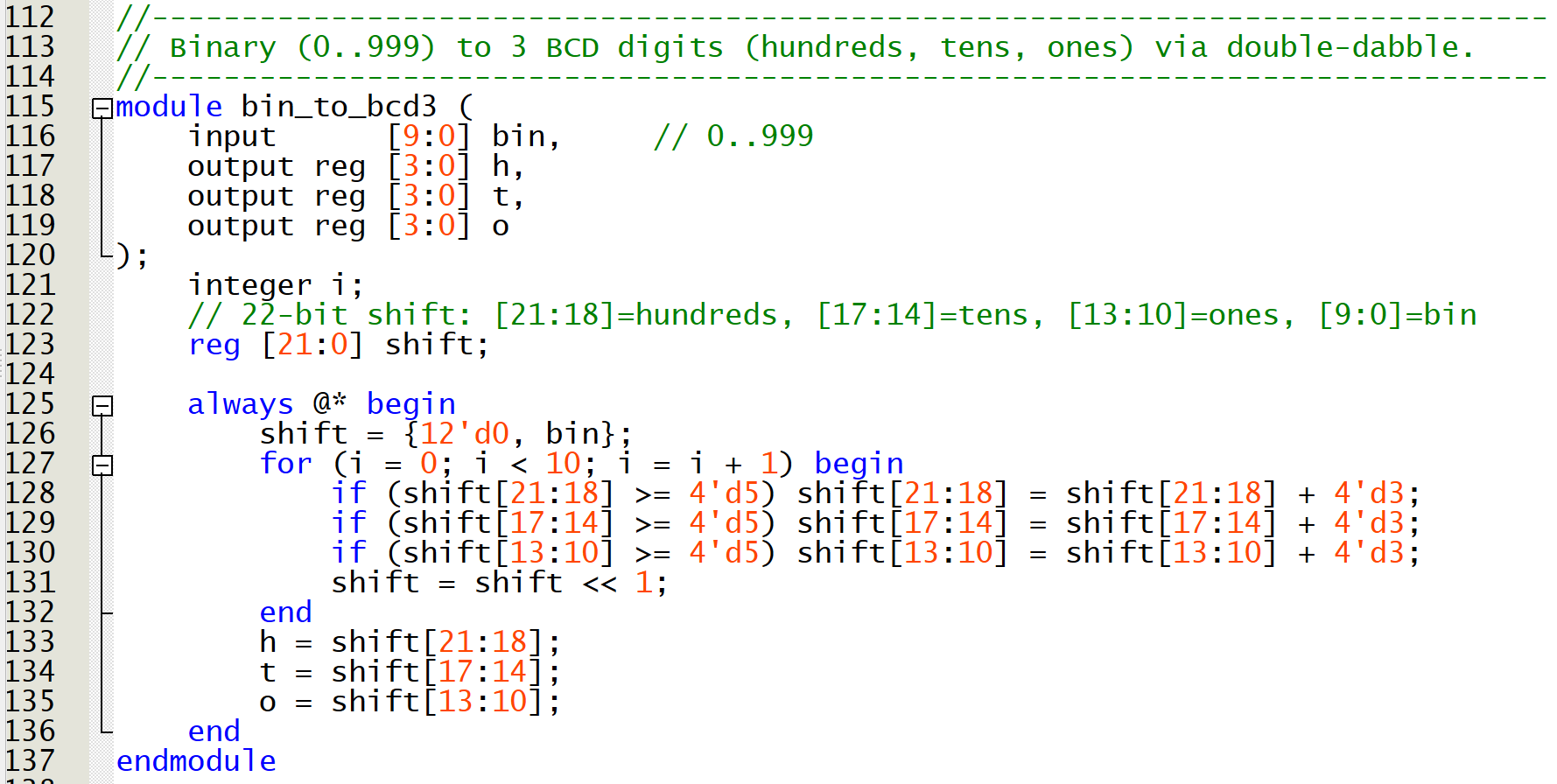
- Lines 62 to 68: convert binary (cm value) to BCD (hundreds (h), tenths (h), zeros(o))
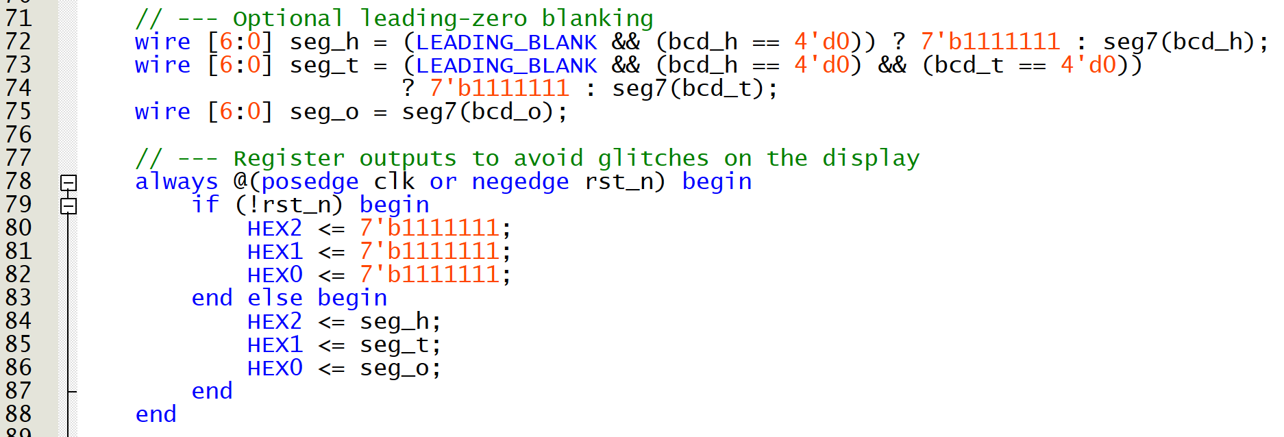
- Lines 72 to 75: convert BCD values to 7 segment display format
- Lines 78 to 88: output value to hex decimal display with sync clock to avoid glitches on the display
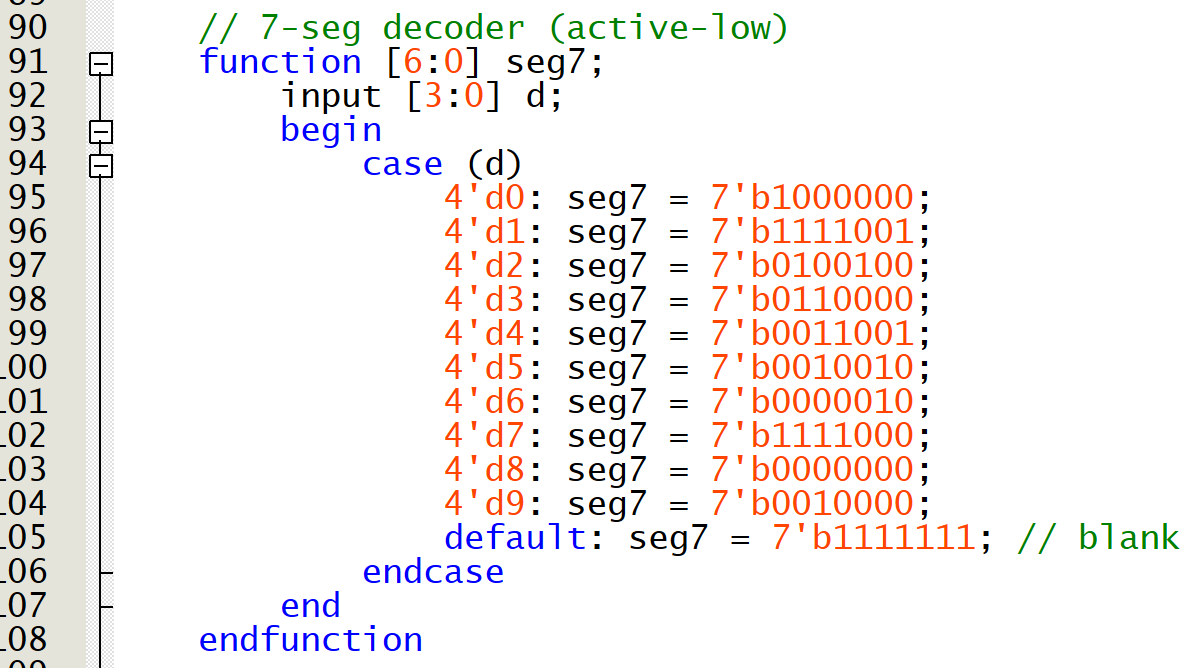
- Lines 91 to 108: 7 segment code display function
- Lines 115 to 137: binary to BCD module converter
RTL Output
Testing Stage
GitHub Repository
References
- Ultrasonic Sensor (HC-SR04) datasheet (Link)